Showing posts with label filter. Show all posts
Showing posts with label filter. Show all posts
Sunday, October 26, 2014
IC 74160 HZ not pass filter
In sometimes when want to decrease especial frequency noise that want only. This circuit can help you , it does will not let 60HZ frequencies s can change. Then decrease the noise. By use the integrated circuit , 741 numbers highly popular , economize and don’t seek buy easy with , if , friends , want to filter especial which frequency the one frequency. As a result change the value RC see the detail has added in the circuit sir.

Thursday, October 23, 2014
Subwoofer Pre Amp Filter
Acoustic spectrum is extended by the 20Hz frequency is very low and reaches as high frequency 20000Hz. In the low frequency is lowered sense of direction. This reasoning leads us to attribute to the speakers use of very low frequency. Making it to you we propose to distinguish these frequencies, in order for him to lead us on a suitable amplifier.
Acoustic filter are met at different points in the sound system. Applications knownest they are filter baxandal to organize low-and high-frequency tones and crossover filter where the acoustics are separated in the subareas, for it leads to the appropriate speakers. Applications that you can we propose is a simple filter that limits the acoustic region (20-20000Hz) in 20-100Hz region.
With manufacturing, we propose that you can you can make an active filter for you lead a very low frequency loudspeaker. With this you will put a big one between speaker HIFI speakers from you. In order for you to have a complete picture of sound you will need also an appropriate amplifier. In the entry of circuit you will connect the two roads out of the preamplifier or the exit of the preamplifier few.
The series production in order to allocate out of the facility led a series of subwoofer power. If for some reason you do not have space for you to put the third speaker in the courtroom, then you can choose a smaller speaker. This output will depend on the type of music that you hear. If in deed you have the space, then after you create a filter and still say thank you, you can he recommend your friends or still makes each other to your friends.
Circuit diagram 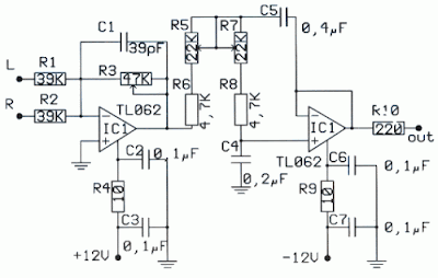 |
| Filter | PreAmp Subwoofer circuit diagram |
Parts
R1 = 39 Kohm , R2 = 39 Kohm,R3 = 47 Kohm,R4 = 10 Ohm,R5 = 22 Kohm,R6 = 4.7 Kohm,R7 = 22 Kohm, R8 = 4.7 Kohm, R9 = 10 Ohm, R10 = 220 Ohm, C1 = 39 pF,C2 = 0.1 UF,C3 = 0.1 UF, C4 = 0.2 UF, C5 = 0.4 UF, C6 = 0.1, UF C7 = 0.1 UF, IC1 = TL064
In the form that appears theoretical filter circuit. At first glance we see three different circuits which are mainly produced by two rounds of operational amplifiers. This circuit is a mixture, with the assistance variable amplifier and variable filters. Late-making requires a series of operations catering catering with the same trend with  ± 12. operational amplifier which is the active element for this circuit is the type of dual operation as a TL082 and NE5532.
The operational amplifier is included in a family is equipped with field-effect transistor IFET in their entries. Each member is allocated a family in bipolar transistor circuits and field effect. This circuit can function in a high inclination, because of their high propensity to use transistors. Also they have the high honor rhythm elevation (slew rate), low polarization at this time for entry and little influenced by temperature. The operational amplifier has an area of 3MHz unity gain bandwidth. Another important element for them is a great choice reject noise, there are currently in the line of catering.
Price refused to greater than 80dB, their consumption is small, from 11 to 3 mA. They briefly sold internally with eight pins and allocate two operational amplifiers, In the same row 14 pin in short they combine four operations, the trade them for sale with code TL074, TL084 and TL064, a nutshell with eight pins they sold the operational amplifier TL071 TL061 kajTL081 . In manufacturing we use the TL082 that has two operational. First operation of TL082 he worked as an amplifier and mixed with two channels, the entry is negative, it is a little mixed with the two resistances. A potentiometer on the steps of determining the aid circuit. At this point the left wing and right-channel preamplifier they added means of two resistances. En operational continuity with the help strengthen the signal is made depending on the price that has been potentiometer.
 |
| PCB layout |
Place runner comparable with the assistance of the circuit. The second operational amplifier is a filter manufacturing. Filters from the acoustic frequency from second grade and he made a round of operational amplifiers. This filter section with variable frequency low-cut. This frequency can be changed and took the price of very low frequency of 30Hz or still exceeds 150Hz. The frequency of the filter depends on the price cuts that have circuit elements. Change the value of the elements that we can have a frequency cut 150Iz, 130Hz, 100Hz, 7A? Z, 6A? Z even 3A? Z, is the price that they can be achieved by simple rotation of the double potentiometer. Filter circuit has been made about an operation that has completed a TL082 dual operational amplifier. In the filter out we will connect the plug load which is connected amplifier. In a series of exit are presented, which are limited as to the extent of frequency, the signal applied in the entry of the circuit.
Friday, September 26, 2014
Switchable Music Rumble Filter Circuit
The switchable rumble filter circuit shown provides a cut-off at 25, 40, or 80Hz. C1 and C2 in con- junction with R3 - 9, form second order Butterworth filters with l2db/ octave roll—off below the turnover frequency.
Unlike most designs, the feedback is taken from the inverting input. ln practice this works well once the signal at this point follows exactly that at the non-inverting input. _ A useful feature is the deep bass boost provided by the feedback loop proper. S2 in position 3 gives a +3db point at l50Hz whilst position 2 provides a +3db point at 150Hz. A supply 6·35V DC at 10mA is required.

Unlike most designs, the feedback is taken from the inverting input. ln practice this works well once the signal at this point follows exactly that at the non-inverting input. _ A useful feature is the deep bass boost provided by the feedback loop proper. S2 in position 3 gives a +3db point at l50Hz whilst position 2 provides a +3db point at 150Hz. A supply 6·35V DC at 10mA is required.
Sunday, August 10, 2014
Antialiasing And Sync Compensation Filter Wiring diagram Schematic
Antialiasing And Sync-Compensation Filter Circuit Diagram. Two dual-bi-quad filter chips and some external components form a multipurpose filter to reconstruct D/A converter signals. Connected to a converter`s output, the filter provides anti-aliasing, reduces the D/A converter`s quantization noise, and compensates for sin(7rx)()—the `sync` function (attenuation). The schema incorporates an inverse-sync function that operates to one-third of the converter`s sample rate. Beyond one-third, the filter`s response shifts to a stop band filter, which provides -70 dB attenuation.
This attenuation conforms to the converter`s inherent signal-to-noise ratio and quantization error. To prevent aliasing, the stop band edge must be no higher than the Nyquist frequency (/„ + 2). To achieve 70-dB stop band rejection with this eighth-order filter requires a transition ratio (/stop band -K/pass band) of 1.5, which sets the passband`s upper limit at fs +3. Notice also that you can apply a simple divide-by-64 schema to the 192-kHz clock frequency to set the necessary 3 ratio between the converter`s sample rate and the filter`s 1-kHz corner frequency.
Antialiasing And Sync-Compensation Filter Circuit Diagram

Subscribe to:
Posts (Atom)