- Simple LED Flasher - Simple LED flasher by using Nutchip.
- AC Powered LED Schematic - Light up LED by using AC supply.
- LED Chaser - Simple LED light chaser.
- Two Transistor LED Flasher - Flashing LED by using transistor.
- 16x16 LED Matrix - Prototype of 16X16 LED
- Battery powers white LED driver
- LED Moon Light
- Tri-color LED Controller with Serial Interface
Schematic Diagram
Monday, January 26, 2015
Circuit Car Battery Saver
I recently forgot to close the door of my car after parking in the garage and I found the battery completely exhausted after the week-end, when I tried to start the engine on Monday morning. This inconvenience prompted me to design a simple circuit, capable of switching-off automatically after a few minutes the inside courtesy lamp, the real culprit for the damage.
Car Battery Saver Circuit Diagram:
Circuit operation:
When the door is opened, SW1 closes, the circuit is powered and the lamp is on. C1 starts charging slowly through R1 and when a voltage of 2/3 the supply is reached at pins #2 and #6 of IC1, the internal comparator changes the state of the flip-flop, the voltage at pin #3 falls to zero and the lamp will switch-off. The lamp will remain in the off state as the door is closed and will illuminate only when the door will be opened again. The final result is a three-terminal device in which two terminals are used to connect the circuit in series to the lamp and the existing door-switch. The third terminal is connected to the 12V positive supply.
Notes:- With the values specified for R1 and C1, the lamp will stay on for about 9 minutes and 30 seconds.
- The time delay can be changed by varying R1 and/or C1 values.
- The circuit can be bypassed by the usually existing switch that allows the interior lamp to illuminate continuously, even when the door is closed: this connection is shown in dotted lines.
- Current drawing when the circuit is off: 150µA.
Tuesday, January 6, 2015
Stepper Motor Driver Circuit Diagram

Using L297-L298 integrated circuits manufactured by SGS Thomson (ST) can be made a control circuit for a stepper motor with two phase bipolar or unipolar four-phase (maximum current allowed on stage is 2 A).
This integrated motor driver generates control signals for the double stator and allows selection of travel direction and execution of a full step or half step, through proper planning its inputs, TTL compatible.
Friday, December 12, 2014
LED Schematic
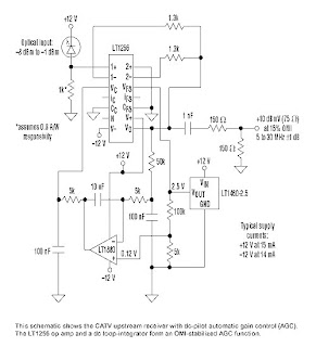
CATV Upstream Fiber Optic Receiver

Upstream fiber links in a community antenna television (CATV) system are usually among the most difficult elements of the network to align properly.Set-top boxes and cable modems employ "long-loop" automatic gain control (AGC) (in other words, far-end power-control), which attempts to normalize the RF path end-to-end.
Alignment is very important because for every decibel of uncorrected optical loss, there's a 2-dB optical-modulation-index (OMI) variance at the transmitting node.
Thermal Fan Controller

The controller uses one or more ordinary silicon diodes as a sensor, and uses a cheap opamp as the amplifier. This circuit designed to be use for 12V computer fans, as these are now very easy to get cheaply. These fans typically draw about 200mA when running, so a small power transistor will be fine as the switch. I used a BD140 (1A, 6.5W), but almost anything you have to hand will work just as well.
Thursday, December 11, 2014
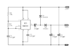
Doubler Voltage with ne555 schematic

This circuit shows a doubler voltage with ne555 schematic.
This be Simple Doubler Voltage circuit, from voltage 12VDC to be 24VDC.
By use Timer IC highly popular the number NE555 and other equipment a little again.
It can give current get about 50mA convenient for the circuit, that use low current the small-sized.
Thursday, November 20, 2014
Create a electric shock resistant tool
Youve electric shock?? .. Well, .. it was nice to recover all your gout! Sometimes true .. but we often do not touch circuit accidentally in the work that is still connected with line / grid (pln) .. pissed, wants I think we stepped on the stuff ..!

Is there any easy way to avoid electric shock in repair work .. can even avoid the occurrence of ESD, if we deal with electronic goods which are sensitive to ESD (PC motherboards, mobile phones, circuit digital etc). you raft just like this series .. used as supply for the solder, when dealing with components which are sensitive to ESD and touch (CMOS IC). the greater capacity of the transformer Ampere. the greater the (good) power which can be handled. The second transformer is identical / similar.
Subscribe to:
Comments (Atom)