Friday, December 12, 2014
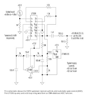
CATV Upstream Fiber Optic Receiver

Wednesday, November 19, 2014
FM Radio Receiver Circuit with IC TDA 7012T

Wednesday, November 5, 2014
A Discharger for Receiver Battery Packs
There are a couple ways you could modify the circuit to work with a 5-cell 6-volt receiver battery pack. The two 1k resistors are a divider network, so one way would be to change the resistors to change the sampling voltage at the comparator. The formula for a divider network is Vout=Vin(R2/(R1+R2)) or R1=R2*((Vin/Vout)-1). Here, R1 is the resistor connected to the positive lead and pin 7 of the comparator, Vin is 5.25 volts (1.05 volts per cell discharge shutoff threshold), and Vout is the reference 2.1 volts (the voltage produced by the LM317T and the 180 and 270 ohm resistors). You can use R2 as the same 1k value that was there before. So R1=1000*((5.25/2.1)-1)=1500=1.5k. So swap the top 1k resistor in the schematic for a 1.5k, and the new shutoff voltage for your device will be 5.25 volts.
To increase the discharge rate, decrease the resistance of the load resistors. You could use four 100 ohm resistors in parallel instead of two, for example, and it would discharge twice as fast. Resistance of a number of resistors in parallel is the value of the resistor devided by the number of the resistors. Here, 100 ohms/ four resistors is 25 ohms. At five volts, current is (5 volts)/(25 ohms)=0.2 ampere or 200mA. Be careful not to decrease resistance too much however--the small signal transistor used in this particular circuit is probably only rated for maximum 500 mA.
Circuit diagram :
Parts:
273-074 Miniature Piezo Buzzer, 12v, PC board mount
271-312 1/4 watt 5% carbon film resistors, 500 pieces (Just do it!)
276-1778 LM317T adjustable voltage regulator
276-1712 Quad comparator LM339
276-1622 LED assortment (20 count)
276-2009 NPN Silicon transistor MPS2222A (2N2222)
Custom electronics:
I post this design not because I think this is a brilliant piece of circuit design but because the design works, and it can give you a start on your own experimentation. The idea is to use the power available from the discharging battery to monitor the voltage of the battery, shut off discharging at a preset voltage (here 1.05 volts/cell), and sound an alarm when discharging is complete. To do so means a voltage reference powered by the changing voltage of the battery, here the LM317T and the 180 with 270 ohm resistors. You could just as easily use a LM336 (see the low voltage warning buzzer page) or a zener with resistor, or something else as a reference. Since the reference voltage must be below the ambient battery voltage, a pair of 1k resistors provides the divided test voltage. The LM339 is a four way comparator.
This design uses really three comparators: in addition to the one driving the transistor, a comparator drives the LED and another drives the buzzer. But you could use a single comparator (like the LM311) with the buzzer across the emitter and collector of the transistor, and the LED in series with a 270 ohm resistor across (parallel with) the 100 ohm load resistors. With the transistor conducting, the voltage drop across base and emitter is low, and the buzzer is quiet. The tiny current in a piezo buzzer (7 mA), when the transistor is not conducting, would be divided between the load resistors and the LED, and the LED is dark.
A word about the comparator.
The output of the comparator serves as a meager source of current, but can sink current nicely. In other words, the high logic output of the comparator will not drive the base of a NPN transistor as here. The 560 ohm resistor provides the current here for the transistor base--the comparator takes it away when its output drops to ground. Hmmm . . . . so, maybe use a PNP transistor like a 2N3906 instead with emitter to + and collector to load, remove the 560 resistor and connect the base through a 1k resistor to the output of the comparator, then reverse the logic of the comparator by swapping the reference with the test. . . hmmmmm. Could work. Yep . . . works.
Monday, September 22, 2014
One Transistor FM Radio Receiver Circuit
Here’s simple FM receiver circuit for a simple superregenerative FM radio. It is sensitive, selective, and has enough audio drive for an earphone. These designs generally have low component counts, however the design or my construction have been far from simple.
FM Radio Receiver Circuit Layout
Because this is a superregenerative design, component layout can be very important. The tuning capacitor, C3, has three leads. Only the outer two leads are used; the middle lead of C3 is not connected. Arrange L1 fairly close to C3, but keep it away from where your hand will be. If your hand is too close to L1 while you tune the radio, it will make tuning very difficult.
Winding L1
L1 sets the frequency of the radio, acts as the antenna, and is the primary adjustment for super-regeneration. Although it has many important jobs, it is easy to construct. Get any cylindrical object that is just under 1/2 inch (13 mm) in diameter. I used a thick pencil from my son’s grade school class, but a magic marker or large drill bit work just fine. #20 bare solid wire works the best, but any wire that holds its shape will do. Wind 6 turns tightly, side-by-side, on the cylinder, then slip the wire off. Spread the windings apart from each other so the whole coil is just under an inch (2.5 cm) long. Find the midpoint and solder a small wire for C2 there. Mount the ends of the wire on your circuit board keeping some clearance between the coil and the circuit board.
A tuning knob for C3
C3 does not come with a knob and I have not found a source. A knob is important to keep your hand away from the capacitor and coil when you tune in stations. The solution is to use a #4 nylon screw. Twist the nylon screw into the threads of the C3 tuning handle. The #4 screw is the wrong thread pitch and will jam (bind) in the threads. This is what you want to happen. Tighten the screw just enough so it stays put as you tune the capacitor. The resulting arrangement works quite well.
FM Radio Receiver Circuit Adjustment
If the radio is wired correctly, there are three possible things you can hear when you turn it on: 1) a radio station, 2) a rushing noise, 3) a squeal, and 4) nothing. If you got a radio station, you are in good shape. Use another FM radio to see where you are on the FM band. You can change the tuning range of C3 by squeezing L1 or change C1. If you hear a rushing noise, you will probably be able to tune in a station.
Try the tuning control and see what you get. If you hear a squeal or hear nothing, then the circuit is oscillating too little or too much. Try spreading or compressing L1. Double check your connections. If you don’t make any progress, then you need to change R4. Replace R4 with a 20K or larger potentiometer (up to 50K). A trimmer potentiometer is best. Adjust R4 until you can reliably tune in stations. Once the circuit is working, you can remove the potentiometer, measure its value, and replace it with a fixed resistor. Some people might want to build the set from the start with a trimmer potentiometer in place (e.g., Mouser 569-72PM-25K).
Sunday, August 31, 2014
Simple Regenerative Receiver Wiring diagram Schematic 80m or 40m
Wednesday, August 20, 2014
Power amplifier for FM radio receiver
Schematic is suitable for use in radio tuner or FM radio receiver when it is assembled and ready for use. Where if the low gear power radio receiver, with the aid of power amplifier is less powerfull voice / hard to better and just right. For use hios speakers , use a low-power , because power amplifier has only the power output of 2 X 5 Watt stereo power amplifeir with impedance of 4 Ohm. Working on a minimum voltage of 4.5 Volts and maximum of 16Volt. Use the correct voltage supply - really have been filtered out in order to improve the performance of these power amplifiers.
Resistor
R1________180R
R2________180R
R3________18K
R4________18K
Capacitor
C1________47uF
C2________4.7uF
C4________100uF
C5________100uF
C6________47uF
C7________4.7uF
C8________47uF
C9________100uF
C10_______100uF
C11_______1000uF
C12_______1000uF
C13_______100pF
C14_______100pF
C15_______68n
C16_______68n
IC
IC1_______TA7215P