Showing posts with label driver. Show all posts
Showing posts with label driver. Show all posts
Tuesday, January 6, 2015
Stepper Motor Driver Circuit Diagram

Using L297-L298 integrated circuits manufactured by SGS Thomson (ST) can be made a control circuit for a stepper motor with two phase bipolar or unipolar four-phase (maximum current allowed on stage is 2 A).
This integrated motor driver generates control signals for the double stator and allows selection of travel direction and execution of a full step or half step, through proper planning its inputs, TTL compatible.

Wednesday, November 12, 2014
using 555 timer ic White led driver circuit with explanation
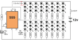
The 555 is capable of sinking and sourcing up to 200mA, but it gets very hot when doing this on a 12v supply.
This white led driver circuit shows the maximum number of white LEDs that can be realistically driven from a 555 timer . The total current was limited to about 130mA as each LED is designed to pass about 17mA to 22mA maximum. A white LED drops a characteristic 3.2v to 3.6v and this means only 3 LEDs can be placed in series.
As you can see in the circuit diagram , this electronic project circuit require few external electronic parts and is capable to drive up to 48 white LEDs from a 12 volts DC power source , utilizing few electronic components .
Friday, October 3, 2014
22W Car Subwoofer Driver
This unit is designed to be connected to an existing car stereo amplifier, adding that often require extra "punch" to music by driving a subwoofer. As the very low frequencies are omnidirectional, a single amplifier is necessary to promote the dedicated speaker.
The power amplifier uses a good and cheap BTL (bridge tied load) 13 pin IC from Philips (now NXP Semiconductors) that require a very low of the parties and capable of delivering about 22 W on a charge of 4 ohms in the battery voltage of 14.4 standard car.
The signals from the stereo line output amplifier car stereo mix in the entry, after the control level, the signal enters the buffer and can be IC1A reversed phase through SW1. This control can be useful to allow the subwoofer to be in phase with the speakers in your car radio today.
Then a variable 12dB/octave filter low pass frequency around IC1B, Q1 and components listed below, which allows precise adjustment of the low pass rate of 70 to 150Hz.
Q2, R17 and C9 form a simple voltage stabilizer for the input and filter circuits, useful to prevent interaction of the positive rail power amplifier to the low-level sections.
Sunday, August 10, 2014
4W Fluorescent lamp driver

This is a 4W fluorescent lamp driver.we can operate this with 12 v battery.so I suppose you can attach this one for your vehicle even. on the other hand you can use this one as an emergency lamp.so try on this be creative to get the maximum harvest.

Notes.
* Assemble the schema on a general purpose PCB.
* The IC 1 must be mounted on a holder.
* Use heat sink for transistor Q1.
* Use a 3 V primary , 230 V secondary, 5W transformer for T1.
* Power the schema from a 12V battery or 12V DC power supply.
* The L1 can be a 6 inch, 4W fluorescent lamp.
Subscribe to:
Posts (Atom)