- Simple LED Flasher - Simple LED flasher by using Nutchip.
- AC Powered LED Schematic - Light up LED by using AC supply.
- LED Chaser - Simple LED light chaser.
- Two Transistor LED Flasher - Flashing LED by using transistor.
- 16x16 LED Matrix - Prototype of 16X16 LED
- Battery powers white LED driver
- LED Moon Light
- Tri-color LED Controller with Serial Interface
Showing posts with label led. Show all posts
Showing posts with label led. Show all posts
Friday, December 12, 2014
LED Schematic

Monday, November 17, 2014
Flip Flop LED
Flip flop circuit is a series of free runing multivibrator given the burden of LEDs on each side of the transition changes its output signal. Flip flop circuit with LEDs is quite simple, that is prepared with 2 units and 2 units of 2N3904 transistor circuit tank circuit composed by the RC circuit. LED indicators signal a change that is placed on each side of the flip flop will be lit in turn by the fire and extinguished the same as the charge and discharge capacitor. Flip flop circuit is quite simple as shown in the picture below.
Flip Flop LED series

The working principle is the flip flop over when the series voltage source is given then the 10uF capacitor will be charged through R 470 and the LED will then be forwarded to triger the transistor base so that the transistor will turn ON and LEDs. this occurs alternately on each side, so that the LED light will illuminate in turn as well.
Wednesday, November 12, 2014
using 555 timer ic White led driver circuit with explanation
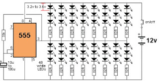
The 555 is capable of sinking and sourcing up to 200mA, but it gets very hot when doing this on a 12v supply.
This white led driver circuit shows the maximum number of white LEDs that can be realistically driven from a 555 timer . The total current was limited to about 130mA as each LED is designed to pass about 17mA to 22mA maximum. A white LED drops a characteristic 3.2v to 3.6v and this means only 3 LEDs can be placed in series.
As you can see in the circuit diagram , this electronic project circuit require few external electronic parts and is capable to drive up to 48 white LEDs from a 12 volts DC power source , utilizing few electronic components .
Tuesday, November 11, 2014
How to Build a Shake Tic Tac LED Torch
In the diagram, it looks like the coils sit on the “table” while the magnet has its edge on the table. This is just a diagram to show how the parts are connected. The coils actually sit flat against the slide (against the side of the magnet) as shown in the diagram:

The output voltage depends on how quickly the magnet passes from one end of the slide to the other. Thats why a rapid shaking produces a higher voltage. You must get the end of the magnet to fully pass though the coil so the voltage will be a maximum. That’s why the slide extends past the coils at the top and bottom of the diagram.
The circuit consists of two 600-turn coils in series, driving a voltage doubler. Each coil produces a positive and negative pulse, each time the magnet passes from one end of the slide to the other.
The positive pulse charges the top electrolytic via the top diode and the negative pulse charges the lower
electrolytic, via the lower diode.
The voltage across each electrolytic is combined to produce a voltage for the white LED. When the combined voltage is greater than 3.2v, the LED illuminates. The electrostatics help to keep the LED illuminated while the magnet starts to make another pass.
Read More..
Shake Tic Tac LED Torch Circuit Diagram
The output voltage depends on how quickly the magnet passes from one end of the slide to the other. Thats why a rapid shaking produces a higher voltage. You must get the end of the magnet to fully pass though the coil so the voltage will be a maximum. That’s why the slide extends past the coils at the top and bottom of the diagram.
The circuit consists of two 600-turn coils in series, driving a voltage doubler. Each coil produces a positive and negative pulse, each time the magnet passes from one end of the slide to the other.
The positive pulse charges the top electrolytic via the top diode and the negative pulse charges the lower
electrolytic, via the lower diode.
The voltage across each electrolytic is combined to produce a voltage for the white LED. When the combined voltage is greater than 3.2v, the LED illuminates. The electrostatics help to keep the LED illuminated while the magnet starts to make another pass.
Saturday, November 1, 2014
Old Mobile Phone Battery for LED lighting
Normally mobile batteries have a lifespan of 2-5 years under normal usage. But then we have to replace them. Nowadays there are cheap replacement batteries which cost no more than 1$. But these low cost batteries run only 6-12 months. What to do with the used batteries, which can’t be reused in mobiles? Well, easy solution is to use the batteries in a circuit that requires less current. We can use them for LED lighting.
Do you have old unusable Mobile battery?
Do you have old unusable Mobile battery?
Normally mobile batteries have a lifespan of 2-5 years under normal usage. But then we have to replace them. Nowadays there are cheap replacement batteries which cost no more than 1$. But these low cost batteries run only 6-12 months. What to do with the used batteries, which can’t be reused in mobiles?
Well, easy solution is to use the batteries in a circuit that requires less current. We can use them for LED lighting. Thus your automatic lighting emergency light is ready which runs by your waste Mobile Battery.
Saturday, October 4, 2014
Simple LED Flasher with 2 Transistor
This is LED Flasher circuit that is built using 2 transistors. Many other NPN transistor have a small signal or switching transistors can be used, such as 2N4401, PN2222 or 2N2222 using the circuit on the left figure. The circuit can also be inverted using PNP transistors such as 2N3906, 2N4403, PN2907, or 2N2907 as shown to the right. This is the figure of the simple LED Flasher circuit;
![]()
The 470 ohm resistors determine the LED brightness. Lower resistance means higher current, and more light. LEDs that require more current or have a higher operating voltage (such as green and yellow) may work better with 300 ohms. The RC time constant of the 39K ohms resistor and the 10uF capacitor determines the on time for each side. (The two sides do not need to match - vary the RC time constant for one side to get a lower or a higher duty cycle). With the values shown, the flash rate is about 1 cycle per second at 50% duty cycle.
The 470 ohm resistors determine the LED brightness. Lower resistance means higher current, and more light. LEDs that require more current or have a higher operating voltage (such as green and yellow) may work better with 300 ohms. The RC time constant of the 39K ohms resistor and the 10uF capacitor determines the on time for each side. (The two sides do not need to match - vary the RC time constant for one side to get a lower or a higher duty cycle). With the values shown, the flash rate is about 1 cycle per second at 50% duty cycle.
Saturday, September 13, 2014
3 LED battery monitor circuit
This is the schema diagram of a 3 LED bar graph type battery monitor schema that is ideal for monitoring the voltage level of an automobile battery
When battery voltage is 11.5V or less transistor Q1 will be On and the LED D1 will be glowing.When battery voltage is between 11.5 and 13.5V, the transistor Q2 will be On and the LED D2 will be glowing.When battery voltage is above 13.5V the transistor Q3 will be On and the LED D3 will be glowing.
Notes.
* Assemble the schema on a general purpose PCB.
* The battery to be monitored can be connected between the terminals namely A and B.
* It is always better to use LEDs of different colour.
Friday, September 12, 2014
0 3 to 1 5V LED Flashlight

Tuesday, September 2, 2014
Reuse Old Mobile Phone Battery for LED lighting
Normally mobile batteries have a lifespan of 2-5 years under normal usage. But then we have to replace them. Nowadays there are cheap replacement batteries which cost no more than 1$. But these low cost batteries run only 6-12 months. What to do with the used batteries, which can’t be reused in mobiles? Well, easy solution is to use the batteries in a schema that requires less current. We can use them for LED lighting.
Do you have old unusable Mobile battery?
![Hacks]()
Normally mobile batteries have a lifespan of 2-5 years under normal usage. But then we have to replace them. Nowadays there are cheap replacement batteries which cost no more than 1$. But these low cost batteries run only 6-12 months. What to do with the used batteries, which can’t be reused in mobiles?Do you have old unusable Mobile battery?
Source by : www.diagramproject.com
Saturday, August 23, 2014
LED Flasher for RC Planes

This is so useful schema for Rc lovers.Because you can use this schema simply for your Rc plane or RC car.Here I have used common IC NE 555.So easily you can find it.

Note
* This schema operates with 6V power supply.
Tuesday, August 12, 2014
230 Blinking LED circuit

This is wonderful schema.Normally we can light up LEDs with 230v.But those are not blinking.This schema shows how to make a blinking LED schema.

Note
# When you use Capacitors use more than 40V
# 230V is dangerous so this schema is not good for kids.
Subscribe to:
Posts (Atom)