Showing posts with label meter. Show all posts
Showing posts with label meter. Show all posts
Saturday, November 8, 2014
Solar Panel Current Meter
This circuit is used to measure the current from a solar panel. It has very low power loss for currents in the 0-10A range. It also works as a general purpose DC current meter. The circuit can be used on either the positive or negative side of a DC circuit.
Solar Panel Current Meter
Specifications
Measured Current: 0-10 Amps DC
Circuit Voltage: Will work with DC circuits at any practical voltage.
Accuracy: approximately 2%, depending on the meter movement.
Theory
The current to be measured flows through the 0.01 ohm resistor which causes a small voltage drop across the resistor. The 100 microamp meter is set up with the series 50 ohm and 500 ohm variable resistor in a voltage measurement configuration to measure this voltage drop. The 500 ohm variable resistor is used to adjust the meters full scale reading. The 50 ohm resistor limits the maximum current to the meter no matter what setting is on the 500 ohm resistor, this protects the meter from passing too much current and burning up. The series resistance of the meter, 500 ohm (or less) variable resistor and 50 ohm resistor should total 1000 ohms. Different meters may require a different variable resistor to achieve the 1000 ohm value.
Construction
Build the meter into a metal box with the meter and two connectors mounted on the outside of the box.
Alignment
Put the meter circuit in series with a known current meter such as a digital VOM meter set to measure current. Run a known current through both meters. Adjust the 500 ohm resistor until both meters read the same current. A good way to get a known current is to put a 12V lead acid battery in series with a 2 ohm 100 watt current limiting resistor. This will produce approximately 6 Amps of current. Put the two meters in series with this loop and adjust for the same reading. Beware, the resistor will get fairly hot in a short time.
Use
Connect this circuit in series with a nominal 12V or 24V solar panel array. The meter can go in either the positive or negative side of the solar panel circuit. The current flowing through the solar panel to the load will be shown on the meter.
Parts
1x 100 microamp DC meter
1x 0.01 ohm 5 W resistor
1x 50 ohm 1/4 W resistor
1x 500 ohm 10 turn variable resistor
2x banana plugs or a 2 pin screw type terminal block.
1x metal box

Tuesday, November 4, 2014
Loudspeaker Impedance Meter
A simple Impedance Meter can be useful to measure the actual impedance a loudspeaker or headphone is presenting @ 1kHz standard frequency. The circuit, designed on request, relies on an earlier design (Spot-frequency Sine wave Generator) to obtain a stable, low distortion 1kHz sine wave avoiding the use of thermistors, bulbs or any special amplitude-limiting device. The sine wave output, after some amplitude setting obtained by means of P1, is sent to the device under measurement through a resistor.
A regulated supply is necessary to obtain a stable output waveform. D1 and D2 force IC1 to deliver 6.2V output instead of the nominal 5V. The measurement is done in two stages: as a constant current supply of the device under test is necessary, this can be set at first by adjusting P1 and measured across the series resistor (R7 or R8, depending on the impedance value to be measured); then, the meter is switched across the device under test and the actual impedance will be read directly on the meter display.
Loudspeaker Impedance Meter Circuit diagram:
P1_______________4K7 Linear Potentiometer
R1______________12K 1/4W Resistor
R2_______________2K2 1/4W Resistor
R3_______________1K 1/2W Trimmer (Cermet)
R4_______________1K5 1/4W Resistor
R5_______________4K7 1/4W Resistor
R6_______________3K3 1/4W Resistor
R7_____________100R 1/4W Resistor (See Notes)
R8_______________1K 1/4W Resistor (See Notes)
R9_______________1K 1/4W Resistor (Optional)
C1______________22nF 63V Polyester Capacitor
C2_____________330nF 63V Polyester Capacitor
C3______________22µF 25V Electrolytic Capacitor
D1,D2_________1N4148 75V 150mA Diodes
D3_______________3mm Red LED (Optional)
Q1,Q2,Q3_______BC550C 45V 100mA Low noise High gain NPN Transistors
IC1____________78L05 5V 100mA Regulator IC
SW1,SW2_________SPDT Toggle or Slider Switches
SW3_____________SPST Toggle or Slider Switch
B1________________9V PP3 Battery
Clip for PP3 Battery
Circuit set-up using an oscilloscope:
Connect the oscilloscope in place of the DVM and rotate P1 fully clockwise.
Short the speaker output and adjust R3 to obtain a sine wave of about 2.2V peak-to-peak amplitude.
"By ear" circuit set-up:
Connect a small loudspeaker or one of the two earpieces forming a pair of headphones to the circuit output and rotate P1 to obtain a moderate output sound level.
Carefully adjust R3 until the output sound will stop; then turn back the trimmer very slowly and stop adjusting immediately when the sound will start again.
Measurement:
- Connect a Digital Voltage Meter set to 200mV ac range to the DVM output terminals
- Connect the device under test to the Speaker terminals.
- Switch SW1 in the position towards R7 if the impedance value to be measured is below 100 Ohm or towards R8 if above.
- With SW2 in the "Set" position power-on the circuit by means of SW3
- Adjust P1 in order to read exactly 100.0mV on the DVM display
- Switch SW2 in the "Measure" position and read directly the loudspeaker or headphones impedance value on the DVM display, e.g. 8.5mV = 8.5 Ohm.
- Please note that when measuring devices with impedance values above 100 Ohm (SW1 set towards R8), the decimal point in the DVM reading must be ignored. E.g. if the display shows 70.5mV, the impedance will be 705 Ohm
- For very precise measurements use 1% or 2% tolerance resistors for R7 and R8.
- D3 LED pilot light and its current limiting resistor R9 are optional.
Wednesday, October 29, 2014
Diagram LM 3915 Sound Level Meter Circuit
Supply voltage can be from 3V to 20V.The input is set for audio line voltage (1V peak to peak) and has a max input voltage of 1.3V. To make the circuit use a moving dot display instead of bar graph display,Pin 9 can be should be disconnected from +V.
Part List
C1 2.2uF 25V Electrolytic Capacitor
C2, C3 0.1uF Ceramic Disc Capacitor
R1, R3 1K 1/4W Resistor
R2 10K 1/4W Resistor
R4 100K 1/4W Resistor
R5 1M 1/4W Resistor
D1 1N4001 Silicon Diode
Q1 BC 558 PNP Transistor
LED1-LED10 Standard LED or LED Array
U1 LM3915 Audio Level IC
MISC Board, Wire, Socket For U1
Sunday, September 7, 2014
Stereo balance meter
Description
Play any stereo disc or tape and then set the amplifier to mono. Adjust left and right channel balance until meter Ml indicates zero; then the left and right output level are identical.
Circuit Diagram
 |
| Stereo balance meter |
Saturday, August 16, 2014
Simple Volt meter Wiring diagram Schematic
This is a simple Volt meters & ampere meter with PIC. This schema used to measure voltage and current simultaneously. The series of volt meters & ampere meter with PIC16F876A PIC is used as a data processor voltage and current are measured.
Simple Volt meter Circuit Diagram
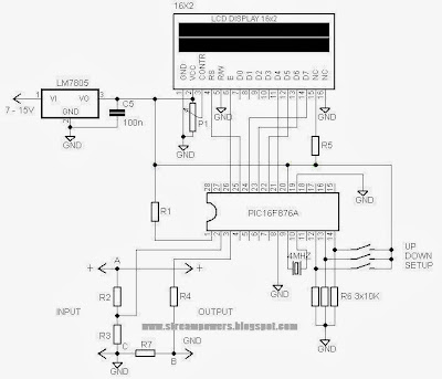
This schema uses the viewer in the form of 16 × 2 LCD used for the data menmpilkan voltage and current measurements. In the article volt meter and ampere meter with PIC are discussed kerannya limited to devices only. More detail can be seen from the image sequence volt meter and ampere meter with PIC below.
Subscribe to:
Posts (Atom)