Showing posts with label of. Show all posts

Wednesday, November 19, 2014

Schematic diagram of a USB player

Usb series player is an electronic device or electronic circuit that functions as an MP3 player that is stored on a storage device such as USB flash.
In this usb circuit using an IC as a modifier of digital voice data into analog so that it can be applied to a headphone, or again through the power amlplifier strengthened so that it can be heard through the speakers. IC used in this circuit using IC PCM2902 as a modifier of a digital data into analog data storage.
Below is a schematic diagram of a USB player.
Schematic usb player
Read More..

Tuesday, November 18, 2014

Function of IC LM35 and How It Works

Do you looking for the function of IC LM35 ? The works of IC LM 35 typically serves as a temperature sensor. IC LM 35 is packaged in the form of integrate circuit which prisoners rates is a function of temperature, the temperature will cause a change of IC LM 35.

Heat energy from the electrodes will cause the IC LM 35 temperature changes that subsequently alter rates prisoners, the characteristics of this sensor is linear to temperature changes means that, if the temperature changes that tend to increase the temperature of the IC will also rise, as well as if the temperature falls.

Images and physical shape of IC LM35
The voltage output from these sensors is ± 10 mu/0C every 10C temperature rise and the largest range of temperatures - 550C to 1150C.
Read More..

Monday, November 17, 2014

Parts of the UPS Uninterruptible Power Supply


Uninterruptible Power Supply
UPS is basically composed of three main components, namely:
1) Rectifier-Charger
This section is used to transfer circuit and battery charging. Rectifier-charger circuit block is going to supply the power needed by the inverter under full load and at that time to maintain the charge in the battery. Besides these blocks must have the ability to drain the power output of 125-130%.

Characteristics of the batteries also need to be taken into account in its charger circuit design because if a rechargeable battery with a current that exceeds the capacity limit will be able to shorten the life of the battery. Usually for a battery charging current to the UPS is 80% of current conditions issued by the batteries at full load.
Limitation of a UPS system is good by the standards of NEMA - National
Electical Manufacturer Association - is able to provide 100% power continuously (continuous load) and 2 hours at 125% load without a decrease in performance (damage). The battery can still be categorized as unfit for use if the condition is still capable of providing 100% power for 1 hour if the time of filling for 8 hours (determined by the manufacturing
battery).

2) Inverter
The quality of the inverter is a determinant of the quality of power generated by a UPS system. Inverter function to change the DC voltage of the rectifier-charger circuit into AC voltage signal in the form of a sine wave formation and after going through the filter circuit. The resulting output voltage must be stable both voltage amplitude and frequency, low distortion, there are no voltage transients.
In addition, the inverter system needs a feedback circuit (feedback) and the regulator circuit to maintain constant voltage to be obtained.

3) Switch Shifters (Transfer switches)
Transfer switch is divided into two types, namely electromechanical and static. Electromechanical switch uses relays to get one of the supply voltage terminal and the other from the UPS system. Static switch system using semiconductor components, such as SCR.
The use of SCR would be better because of the removal operation is performed with the SCR takes only 3 to 4 ms, while the electromechanical switch is about 50 to 100 ms.
The use of UPS is done by connecting the UPS to the AC input and output PLN UPS to the load. Most UPS are used to supply the computer, because if the source of PLN suddenly dies, then the data being processed is not lost but is still in the back-up by UPS, so theres still time to save data.
Read More..

Wednesday, October 29, 2014

Circuit Diagram of Remote Control Tester

Here is an infrared remote control tester circuit that can be made without spenting much money.This IR tester build around an infrared reciever module TSOP1738. We can observe the remote control state by listening to the buzzer sound. The circuit is very sensitive and it support a range of about 5 meters.

The infrared receiver module normally remains high and the piezo buzzer is in silent mode. When the IR module receives a signal from the remote control,Its output goes low and the piezo buzzer sounds.

Circuit

Notes
  • Assemble the circuit on a Common PCB and enclose in a small box.
  • Make sure the IR receiver made visible outside.
  • You can directly plug the circuit into mains
Read More..

Sunday, October 5, 2014

with TDA7294 Project of circuit potent audio amplifier
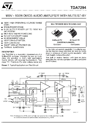
Super Amplifier with tda7294 of the St microeletronics, is possible to get potency of up to 100W in an only chip, for an unit stereo to use two same to that. That circuit is based on the datasheet of the ready to work with sources of strong signs, in case it is necessary it uses a pré-amplifier in the form of an opamp. That circuit type with integrated circuit is ideal for systems of involving sound. Because he is quite compact could use an independent amplifier for each one of the high speakers. In that way it can be to share the source dimensioned it is clear to support all the connected amplifiers.

dmos

schematic - diagram circuit for assembly power amplifier tda7294

schematic 

lists of components: for tda7294

C1 1µF
C2 47µF
C3 10µF
C4 10µF
C5 22µF
C6 4700µF/50V
C7 100N
C8 4700µF/50V
C9 100N
D1 1N4148
R1 22K
R2 680R
R3 22K
R4 22K
R5 30K
R6 10K
SL1 key de Mute
SL2 signal input (Line In)
U1 TDA7294V
X2 Connector AK300/3
X3 Connector AK300/2
several: Printed circuit board, power source +35 -35V / 6A, etc
Read More..

Tuesday, September 23, 2014

General purpose power supply with LM723 and TIP31 circuit


This general purpose power supply can e used for supply output voltages from 1 to 35V. The line transformer should be selected to give about 1.4 times the desired output voltage from the positive side of filter capacitor C1 to ground. Potentiometer R2 sets the output voltage to the desired value by adjusting the reference input.

Rsc is the current limit set resistor. Its value is calculated as:
Rsc = 0.65V/IL
For example, if the maximum current output is to be 1A, Rsc = 0.65/1 = 0.65?
The 1k? resistor, Rs, is a light-loaded resistor designed to improve the no-load stability of the supply.

Read more source:

http://apowersupply.com/general-purpose-power-supply-37.html

Read More..

Sunday, September 21, 2014

Project of circuit potent audio amplifier with TDA7294

Super Amplifier with tda7294 of the St microeletronics, is possible to get potency of up to 100W in an only chip, for an unit stereo to use two same to that. That circuit is based on the datasheet of the ready

to work with sources of strong signs, in case it is necessary it uses a pré-amplifier in the form of an opamp. That circuit type with integrated circuit is ideal for systems of involving sound. Because he is quite compact could use an independent amplifier for each one of the high speakers. In that way it can be to share the source dimensioned it is clear to support all the connected amplifiers. Oh you can remove a wave with that neighbor that bought a " home theater " of 1000W PMPO, and fear in saying that is an enormous potency, when in reality it will verify the real potency of the equipment it doesnt arrive nor to 10W RMS for channel. It already imagined a system of high active speakers with 80W. If it will pass for the marketing department, that where defines the potency PMPO, your system would give... it lets me to see... comparing with the example oh of top... about " 3000 W PMPO ". Game that you have been doing with the potency of the equipments. For you to do your sound system will only need the sign source. Because the amplifier can be perfectly that of here. The necessary subwoofer of a little more of potency then in the datasheet you will find an assembly example in bridge to increase the potency. Below we have the schematic, the Printed circuit board and details of the assembly.

Good luck.

dmos

schematic - diagram circuit for assembly power amplifier tda7294

schematic

Suggestion of Printed circuit board to assembly the power amplifier with tda7294

printed

Side of the components to assembly potent amplifier with TDA7294

Plate 3d

lists of components: for tda7294

C1 1µF
C2 47µF
C3 10µF
C4 10µF
C5 22µF
C6 4700µF/50V
C7 100N
C8 4700µF/50V
C9 100N
D1 1N4148
R1 22K
R2 680R
R3 22K
R4 22K
R5 30K
R6 10K
SL1 key de Mute
SL2 signal input (Line In)
U1 TDA7294V
X2 Connector AK300/3
X3 Connector AK300/2
several: Printed circuit board, power source +35 -35V / 6A, etc
Read More..

Thursday, September 18, 2014

Fuse Panel Diagram Of 1997 Ford Taurus

Fuse Panel Diagram Of 1997 Ford Taurus
The following circuit shows about Fuse Panel Diagram Of 1997 Ford Taurus. The parts fuse panel consist of: data link connector, shift lock actuator, remote anti theft personality.fuel sensor module, blend dock actuator, blower resistor, air temperature door variable resistor, anti theft system, heater function selector, integrated controls, one touch window door relay, window defrost, interior lamps, electronic flasher, door lock relay, blower switch, instrument cluster, generic electronic module.
Read More..

Wednesday, September 17, 2014

Fuse Panel Diagram Of Mustang SN95 4 6 Tech

Fuse Panel Diagram Of Mustang SN95 4.6 Tech
The following circuit shows about Fuse Panel Diagram Of Mustang SN95 4.6 Tech. The parts fuse panel consist of: GEM, Interior Lamp, Engine Control, Traction Control Switch, Engine Control, Reversing Lamp, Electronic Flasher, Power Lumbar Seats, Starter Motor Relay, RH Low Beam Headlamp, Instrument Cluster, LH Low Beam Headlamp, Cigar Lighter.
Read More..

Friday, August 29, 2014

Self Installation of Auto Sound System can Save Serious Cash

If you are seriously hoping to save a significant chunk of change when it comes to your auto sound system, you should consider saving on installation. Under ordinary circumstances I urge people to be very, if not overly cautious when it comes to installing your own auto sound systems. The thing is, that some people really are talented when it comes to activities such as this. Beyond talent, some people have frightening skills with electronics and if you are one of those, then by all means consider the money you could save yourself (or the extra money youd have to invest in your system?).


We all know that money doesnt grow on trees and when youve been saving up for quite a while to get the sound system you really want its a serious joy killer to have to wait another month or two in order to save up enough money to cover the cost of the installation of your sound system. If you or someone you know and trust (trust being the operative word in this instance) can do the work, it makes no sense from a fiscal point of view to pay someone else to do it.

That being said, if there are any doubts about your skill or experience you might want to at the very least get a second opinion or price installations in your area to see if it might actually be worth saving a little more. Time is another important issue when it comes to the installation of an auto sound system. It doesnt matter how capable you are of making the installation if you simply lack the time to do it. In cases such as this it would have been just as wise to go ahead and pay someone to make the installation. It makes much more sense to me than having the system sitting in a box for months on end while you wait for the time to get it taken care of.

I am one of those people who firmly believes that time is money. Time lost from work is expensive. This is especially true when the times of 10 or more people are lost. It adds up quickly no matter if you have a small or a large company. Time is also (unfortunately) the one commodity in life that you can never recover. No matter how hard you try you cannot recapture time that has been lost. If you have children you know exactly what Im talking about (particularly if your children are either teens or grown and gone). You cannot recover lost time so make sure you arent wasting your time by trying to install an auto sound system that is beyond your abilities.

Dont fret though. Most of us find that at some point in our lives we are limited by either time or money if not both. If everything was quick and easy we wouldnt really have anything worth working for would we? Consider all your limitations when planning and purchasing your auto sound system and make sure that the system you select falls squarely within your ability to install, your time limit for installation, or your price range for affording to pay for the installation. Whether you decide to do your own installation or have a professional installation of your auto sound system the prize is the superior sound quality you will be able to enjoy.

Read More..

Thursday, August 21, 2014

Workings of STR IC Regulator Power Supply

The meaning STR in this article for example is a Sanken regulator series and Fairchild series STR-F/G/W KA05Q Is an ic Quasy Resonant Flyback (QRF) Swiching Regulator comprising (a) control IC and (b) power MOSFETs that are packed into a single unit. The regulator is designed so that only requires a few external components.

How it works :
A. UVLO (under voltage lock out)
Regulators will start working when the voltage Vcc start-up on pin-4 reaches 16V. Once the power supply voltage Vcc further work will be reimbursed through a switching transformer supplied from a diode rectifier. At the time the circuit was working when the voltage Vcc is less than 15V, the regulator controls will still work. regulator will stop working (protectionism) if the supply voltage Vcc drops to less than 11V.
  
2. Feedback control (pin-1)
Workings
PWM regulators work using the system, wherein the output voltage B + to stable controlled by the feedback circuit of the output voltage B + >>> >>> photo-coupler pin-1. A capacitor mounted on the pin-1 is used to prevent noise disturbance if anyone does not interfere with the working system.

  
3. Soft start (pin-5)
When the power is turned on first, then the circuit has not been working behind the Uman because there is no output voltage B +. This causes a heavy current on the MOSFET start. To prevent this, the regulator is equipped with soft start circuit internally and an external filter kapasitr.
If the power supply is used to monitor for example, the frequency of the regulator needs to be synchronized. External synchronization signal can be input through pin-5s
  
4. Protectors
Regulators are equipped with all sorts protector.
  • Over-current protector (OCP) or Over Load protector (OLP). For example, if there is damage to flyback or def yoke, it will cause the load voltage B + over. If there is such a case the regulator will die protectionism so that IC is not damaged. For over current sensor is a resistor with a small value that is placed on pin-2 to the ground.
  • Short protector. If the output voltage B + short, the regulator turns off protectionism.
  • Over-voltage protectors (OVP). Regulators are not equipped with a surge protector so if the feedback path disconnected can cause the output voltage of the transformer switching regulator power up or damaged .. With OVP protectionist regulator will die if the voltage supply Vcc pin-4 rise above 22.5v.
  • Thermal protector. Regulators will stop working if the temperature reaches 140 degrees Celsius.
6. Auto start.
Regulators will start automatically if the auto turns itself (protectionism) after OVP or OCP


read also ->>>> Troubleshooting STR IC Regulator Power Supply
Read More..