Showing posts with label low. Show all posts

Tuesday, September 23, 2014

Low Noise Variable Output 1 25V to 12Vdc


This circuit is DC converter low voltage , 12V from be 1.25V to 10Vdc by can give current topmost get about 1.5A. You should use IC number LM317K because have electric many power more the number LM317T. By should hold heat sink. That have large-sized with. The R4 use for fine decorate voltage output. The C1,C3 , and , C2 , for decrease all noise well. The detail is other , see in the circuit.
circuit source by joe (aircraftdesigner)
Read More..

Monday, September 15, 2014

Low cost Pump Controller Wiring diagram Schematic

This simple but effective schema can be used to control water level in a container. The prototype is used to pump water out of a bucket that collects condensation from a home air-conditioning system. The design is based around a 555 timer (IC1). Although the timer in configured as a mono-stable, it lacks the usual timing capacitor from pin 6 to ground. Instead, a metal probe inserted in the water provides a current path to a second, grounded probe. When the water level in the container reaches a third ("high") probe, the trigger input (pin 3) is pulled low, switching the 555 output high and energizing the relay via transistor Q1.

Circuit diagram:

cheap-pump-controller-schema 
Cheap Pump Controller Circuit Diagram

Once the water level drops below the "low" probe, the threshold input (pin 6) swings high, switching the output (pin 3) low and the relay and pump off. The two 100kΩ pull-up resistors can be replaced with larger values if more sensitivity is required (eg, if the 555 doesn’t trigger). A switch (S1) can be included to bypass the relay for manual emptying. The "low" probe should be positioned so that the pump doesn’t run dry.

cheap-pump-controller

The high level probe is placed at the level that you want the pump to start. Since the water is held at ground potential, you must use stainless steel or copper wire to slow corrosion. With water fountain pumps available for less than $10, this schema offers a cheap alternative for those who have an air-conditioner on an internal wall and don’t want to be continually emptying the bucket on humid days.
Source by : Streampowers
Read More..

Sunday, August 31, 2014

Low cost intregated circuit audio power amplifier

KA2201
This amplifier circuit is very cheap, because not a lot of components that are required, and the voltage or amperage required is also not too large, so the transformer or power supply is also quite cheap. IC which can be used in power amplifier circuit is the KA2201, LM820M, TBA820M, U820. This amplifier output of 2 W and 4 ohm impedance, which can be applied to the speaker with 4W power, on such small speakers in front of a PC. For the required minimum input voltage of 3 volts and a maximum of 16 volts, for the recommended voltage of 12 volts.
Parts

Resistor
R1 = 100K
R2 = 120R
R3 = 100R
R4 = 10R

Capacitor
C1 = 0.1uF
C2 = 100uF
C3 = 47uF
C4 = 100uF
C5 = 470uF
C6 = 220pF
C7 = 100nF

IC
U1 = KA2201 , LM820M, TBA820M, U820
Read More..

Friday, August 29, 2014

Battery Switch With Low Dropout Regulator

In the form of the LT1579 Linear Technology (www.linear-tech.com) has produced a practical battery switch with an integrated low-dropout regulator. In contrast to previous devices no diodes are required. The schema is available in a 3.3 V version (LT1579CS8-3.3) and in a 5 V version (LT1579CS8-5), both in SO8 SMD packages. There is also an adjustable version and versions in an SO16 package which offer a greater range of control and drive signals. The main battery, whose terminal voltage must be at least 0.4 V higher than the desired output voltage, is connected to pin IN1. The backup battery is connected to pin IN2. The regulated output OUT can deliver a current of up to 300 mA. The LDO regulator part of the IC includes a pass transistor for the main input voltage IN1 and another for the backup battery on IN2.

 Battery Switch With Low-Dropout Regulator schema Diagram

Battery


The IC will switch over to the backup battery when it detects that the pass transistor for the main voltage input is in danger of no longer being able to maintain the required output voltage. The device then smoothly switches over to the backup battery. The open-drain status output BACKUP goes low to indicate when this has occurred. When neither battery is able to maintain the output voltage at the desired level the open-drain output DROPOUT goes low. The LT1579 can operate with input voltages of up to +20 V from the batteries. The regulator output OUT is short-schema proof. The shutdown input switches off the output; if this feature is not required, the input can simply be left open.

Read More..

Tuesday, August 26, 2014

Simple Low Cost 100W Inverter

Here is the schema diagram of a simple 100 watt inverter using IC CD4047 and MOSFET IRF540. The schema is simple low cost and can be even assembled on a veroboard. Circuit diagram : Simple Low Cost 100W Inverter Circuit Diagram CD 4047 is a low power CMOS astable/monostable multivibrator IC. Here it is wired as an astable multivibrator producing two pulse  trains of 0.01s which are 180 degree out of phase at the pins 10 and 11 of the IC. Pin 10 is connected to the gate of Q1 and pin 11 is connected to the gate of Q2. Resistors R3 and R4 prevents the loading of the IC by the respective MOSFETs. When pin 10 is high Q1 conducts and  current flows through the upper half of the transformer primary which accounts for the positive half of the output AC voltage. When pin 11 is high Q2 conducts and  current flows through the lower half of the transformer primary in opposite direction and it accounts for the negative half of the output AC voltage.

Notes.

  •     B1 can be  a 12V/ 6Ah lead acid battery.
  •     Q1 and Q2 must be fitted to a proper heat sink.
  •     T1 can be a 9-0-9 V primary, 230V secondary, 150VA transformer .
  •     Do not expect much from this schema. The is very simple one suitable for low grade applications.

Read More..

Wednesday, August 20, 2014

500W Low Cost 12V to 220V Inverter Wiring diagram Schematic

Attention: This Circuit is using high voltage that is lethal. Please take appropriate precautions

Using this schema you can convert the 12V dc in to the 220V Ac. In this schema 4047 is use to generate the square wave of 50hz and amplify the current and then amplify the voltage by using the step transformer.

How to calculate transformer rating

The basic formula is P=VI and between input output of the transformer we have Power input = Power output

For example if we want a 220W output at 220V then we need 1A at the output. Then at the input we must have at least 18.3V at 12V because: 12V*18.3 = 220v*1

So you have to wind the step up transformer 12v to 220v but input winding must be capable to bear 20A.


500W
Read More..

Friday, August 8, 2014

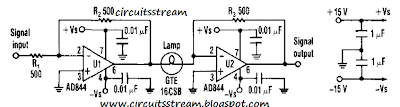
Build a Low Distortion Amplifier cum Compressor Wiring diagram Schematic

Build a Low Distortion Amplifier cum Compressor Circuit Diagram. Designers can build a 15-dB compressor with a miniature lamp and a current-feedback amplifier. The schema possesses extremely low distortion at frequencies above the lamp`s thermal time constant. This means that distortion is negligible from audio frequencies to beyond 10 MHz. There`s also relatively little change in phase versus gain compared to other automatic gain-control diagram. Lastly, the schema has many instrumentation, audio, and high-frequency applications as a result of its low distortion and small phase change. 

The AD844 op amp is a perfect fit for this application because it`s a current-feedback amplifier. Each stage of the schema, U2, lamp, and feedback resistor compresses an ac signal by over 15 dB (see the figure). Cascading a number of stages delivers higher compression ranges. Op amp U1 operates as a unity-gain buffer to drive the input to the compressor. However, U1 is optional if a low-impedance signal source is used. 

Low Distortion Amplifier cum Compressor Circuit Diagram

 Low Distortion Amplifier cum Compressor Circuit Diagram


The lamp`s resistance will increase with temperature, which reduces the ratio of resistor R3 to the resistance of the lamp. This ratio reduces the gain of U2. The lamp`s cold resistance should be greater than the input resistance of U2 (more than 50 ) for proper operation. The lamp`s resistance will change slightly for low input levels. Therefore, the ratio of R3 to the resistance of the lamp and the gain of U2 stays high.
Read More..