Showing posts with label lcd. Show all posts
Showing posts with label lcd. Show all posts
Wednesday, September 3, 2014
DELL E1909WDD 19 LCD Color Monitor SMPS and Back light Inverter Troubleshooting
Dell E1909WDD - 19" LCD Color Monitor Power Supply and Backlight Inverter – Troubleshooting & Schematics
[CLICK ON THE PICTURES TO MAGNIFY]


Saturday, August 30, 2014
Build a Lcd Display Power Supply Wiring diagram Schematic
This is the simple Lcd Display Power Supply Circuit Diagram. Laptop computers often use large-screen LCDs, which require a variable and a negative supply to ensure maximum contrast. This schema operates from the system`s positive battery supply and generates a digitally variable negative voltage to drive the display. This figure`s switching regulator creates a negative voltage from the battery supply. The microprocessor data bus drives a 4-bit DAC, which in turn varies the actual regulator output from - 6.5 to -11.5 V.
Lcd Display Power Supply Circuit Diagram

This arrangement allows a staircase of 16 possible voltages between these limits. The schema implements the DAC by using the rail-to-rail output-drive capability of a 74 HC-series CMOS gate. A resistor divider network formed by the 240-kfi resistor, connected to the -V filter capacitor and the resistors, is referenced to the 5-V supply control (the MAX635 regulator).
When the voltage at the VFb pin is greater than ground, the switching regulator turns on. The inductor dumps this energy into the -V filter capacitor. When the voltage at VFb is less than ground, the regulator skips a cycle. The MAX635 regulates the voltage at the junction of the resistor divider to 0 V. Thus, any resistor that the DAC connects to ground (logic 0) will not contribute any current to the ladder. Only the resistors that are at 5 V (logic 1) will be part of the voltage-divider equation.
The entire switching-regulator supply draws less than 150 . You can place the schema in an even lower power mode by interrupting the ground pin. The high-current path is from the battery input through the internal power PMOSFET to the external inductor. Disconnecting the ground connection simply disables the gate drive to the FET and turns off the internal oscillator.
Friday, August 15, 2014
HOW TO DISASSEMBLE DELL E1909 19” LCD MONITOR
Dell E1909_19" lCD Monitor_Disassemble Procedure. [Horizontal Frequency: 30 kHz to 83 kHz]
Click on the pictures to Zoom In

* Put the monitor on the soft plane table, to avoid scrapping the panel.
* Remove the cable cover as the arrow shown.
* To remove stand press the button at the same time pull out the hinge cover follow the arrowhead direction and remove it, then remove the hinge.
* Remove the four screws and remove the base.
* Pry the monitor up then find out the hooks’ position, use the tool (like the picture or other card) to insert into the gap of bezel and rear cover, then turn over the monitor and take off the rear cover.
* Remove the key board: Remove the screws marked in red.

* Disconnect connector remarked in green.
* To remove shield: Remove the four screws and remove the main frame by manual or torque = 3kgF.Cm and disconnect connector marked in green.

*To remove the power board: Remove the screws remarked in red.

Wednesday, August 13, 2014
Displaying custom character in lcd using MikroC

Suppose you have to display a heart or love sign or any other logo to your lcd display. So lets make a trial.Its easy if you are simply go through this tutorial. MikroC has a powerful tool to display custom character in lcd.
You can draw custom character using this tool and it returns necessary codes for you.
In this tutorial we design + sign first ,and simulate it using proteus to view the result.
First open MikroC PRO for PIC and make a new project using pic16f73 with clock 20MHZ.
Go to Tools->LCD Custom Character

In next window design + sign by clicking rectangular boxes.Then press enter to generate code. Copy the full code to the.

Then paste the code under void main section shown below.Change the line
To this linevoid CustomChar(char pos_row, char pos_char)
void CustomChar1(char pos_row, char pos_char)
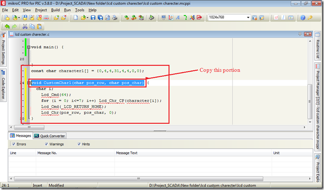
Then copy this line before void main shown below

Now just initialize lcd and call custochar1() in row 1 col 1 by writing
Lcd_Init(); // Initialize LCD
CustomChar1(1,1); //print + in lcd position row 1, column 1

Then Build the project and collect the hex file.
Open Proteus and draw the schema as shown below.
Load the hex file and in pic and oscillator will be 20 MHz.Then Run

Okey That’s Done!!!
Adding more characters
To add more character repeat the process again and now we shall design x sign with nameCustomChar2();But here is problem you have to face if you call
CustomChar2(1,3);You may see both
+ +sign rather than
+ xTo fix this problem you have change some code

Make two changes shown in figure above.
write
Lcd_Cmd(72); //every new character needs to add 8 e.g: 64+8=72rather than
Lcd_Cmd(64);And
Lcd_Chr(pos_row, pos_char, 1); //1 for 2nd characterrather than
Lcd_Chr(pos_row, pos_char, 0);Finally another divide sign I create named
CustomChar3();Call all three character at a time
void main() {Build the project and run in proteus. Output window I have
Lcd_Init(); // Initialize LCD
CustomChar1(1,1); //print + in lcd position row 1, column 1
CustomChar2(1,3); //print x in lcd position row 1, column 3
CustomChar3(1,5); //print Devide sign in lcd position row 1, column 5
}
Now you can design any custom character you need.
You can download the full project file from here Lcd Custom Character.rar
The proteus DSN file is here Lcd Custom character.DSN
Subscribe to:
Posts (Atom)