Thursday, November 13, 2014
Burglar Alarm Using LDR and BC 548
.When the light coming towards the ldr during the period the ldr have low resistance so the buzzer will on.When the light going away the ldr during the period the ldr have high resistance so the transistor will off.Here you need a 12 volt power supply

Components Required Resistor
10 k(preset)
Transistor
BC 548
LDR
Buzzer
Source by : http://www.electronics-circuits.in/2012/03/burglar-alarm-ldr-bc-548.html

Ceiling Fan Regulator Circuit Motor Speed Controller
Circuit Diagram of Ceiling Fan Regulator :
 |
| Fig: Ceiling fan regulator (AC motor speed controller) Circuit Diagram |
Pin Diagram of TRIAC(T1)- Z0607:
 |
| Fig: Z0607-TRIAC Pin diagram |
Pin Diagram of Variable Resistor R1:
| Fig: Pin Diagram of Variable Resistor |
Parts List Of Ceiling Fan-Motor Speed Controller circuit:
T1 = Z0607 -TRIACD1 = DB3 C312 -DIAC
R1 = 500KΩ -Variable Resistor
R2 = 37KΩ -Resistor
C1 = 2A104J -Polyester film capacitor.
M1 = Single Phase AC Motor (Ceiling Fan)-220V,50Hz
Wednesday, November 12, 2014
Remote Operated Home Appliances Circuit
Circuit diagram:
Parts:
R1 = 220K
R2 = 330R
R3 = 1K
R4 = 330R
R5 = 47R
C1 = 100uF-16V
C2 = 100nF-63V
C3 = 470uF-16V
D1 = 1N4007
D2 = Red LED
D3 = Green LED
Q1 = BC558
Q2 = BC548
IR = TSOP1738
IC1 = CD4017
RL1 = Relay 5V DC
Circuit Operation:
The 38kHz infrared rays generated by the remote control are received by IR receiver module TSOP1738 of the circuit. Pin 1 of TSOP1738 is connected to ground, pin 2 is connected to the power supply through R5 and the output is taken from pin 3. The output signal is amplified by Q1. The amplified signal is fed to clock pin 14 of decade counter IC CD4017 (IC1). Pin 8 of IC1 is grounded, pin 16 is connected to vcc and pin 3 is connected to D2 (Red LED), which glows to indicate that the appliance is ‘off.’
The output of IC1 is taken from its pin 2. D3 connected to pin 2 is used to indicate the ‘on’ state of the appliance. Q2 connected to pin 2 of IC1 drives relay RL1. D1 acts as a freewheeling diode. The appliance to be controlled is connected between the pole of the relay and neutral terminal of mains. It gets connected to live terminal of AC mains via normally opened (N/O) contact when the relay energizes. If you want to operate a DC 12 volt relay then use a regulated DC 12 volt power supply for DC 12 volt Relay and remember that the circuit voltage not be exceeded more than DC 5 volte.
using 555 timer ic White led driver circuit with explanation
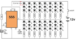
The 555 is capable of sinking and sourcing up to 200mA, but it gets very hot when doing this on a 12v supply.
This white led driver circuit shows the maximum number of white LEDs that can be realistically driven from a 555 timer . The total current was limited to about 130mA as each LED is designed to pass about 17mA to 22mA maximum. A white LED drops a characteristic 3.2v to 3.6v and this means only 3 LEDs can be placed in series.
As you can see in the circuit diagram , this electronic project circuit require few external electronic parts and is capable to drive up to 48 white LEDs from a 12 volts DC power source , utilizing few electronic components .
IC TDA7012T Mini FM Received Based on Single FM circuit with explanation
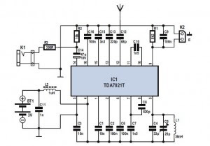
Mini FM Received Circuit
TDA7021T chip radio receiver ambit is for carriageable radios, stereo as able-bodied as mono, area a minimum of ambit is important in agreement of baby ambit and low cost. It is absolutely accordant for applications application the low-voltage micro affability arrangement (MTS). The IC has a abundance bound bend (FLL) arrangement with an average abundance of 76 kHz. The selectivity is acquired by alive RC filters.
The alone action to be acquainted is the beating abundance of the oscillator. Interstation babble as able-bodied as babble from accepting anemic signals is bargain by a alternation aphasiac system.
Part List:
R1 = 8kΩ2
R2 = 10kΩ
R3 = 390Ω
C1,C3 = 10nF
C2,C6,C9,C16 = 100nF
C4 = 33pF
C5 = 25pF trimmer (Murata type TZB4Z250AB10R00)
C7,C10 = 1nF5
C8 = 820pF C11 = 1nF
C12 = 68pF
C13 = 220pF
C14 = 47μF 10V (Nichicon UWX1A470MCL1GB 5.5mmL chip type)
C15 = 3nF3
L1 = 36nH (4 turns 0.5mm silver-plated wire, inside diameter 4mm; length 7mm)
L2 = 1μH, SMD case 0805 (fres > 300 MHz)
IC1 = TDA7021T (SMD in SO16 case)
Simple Police Siren
Tuesday, November 11, 2014
How to Build a Shake Tic Tac LED Torch
The output voltage depends on how quickly the magnet passes from one end of the slide to the other. Thats why a rapid shaking produces a higher voltage. You must get the end of the magnet to fully pass though the coil so the voltage will be a maximum. That’s why the slide extends past the coils at the top and bottom of the diagram.
The circuit consists of two 600-turn coils in series, driving a voltage doubler. Each coil produces a positive and negative pulse, each time the magnet passes from one end of the slide to the other.
The positive pulse charges the top electrolytic via the top diode and the negative pulse charges the lower
electrolytic, via the lower diode.
The voltage across each electrolytic is combined to produce a voltage for the white LED. When the combined voltage is greater than 3.2v, the LED illuminates. The electrostatics help to keep the LED illuminated while the magnet starts to make another pass.